Synthesis 101 | Introduction to Control Voltage (CV)

TABLE OF CONTENTS
- Introduction to Control Voltages
- Controlling Your Modular Synth with the CV Output of a MIDI Keyboard
- Clocking Between Multiple Semi-Modular Synthesizers
- Bipolar & Unipolar Voltage
- Attenuator & Attenuverter
- CV Offset
- CV Guidelines (Voltage Height Standards)
Introduction to Control Voltages
Control voltages (CV) are analog voltage signals used to regulate operational parameters within electronic synthesis systems. These signals provide continuous, real‑time control over functions such as oscillator pitch, filter cutoff frequency, and modulation depth, enabling precise and expressive sound shaping.
In an analog environment, CV is typically produced by devices such as sequencers, keyboard controllers, or dedicated modulation sources. The resulting voltage is routed to a destination module, where its amplitude directly determines the behavior of the controlled parameter. Because CV is continuous rather than quantized, it supports smooth transitions and evolving timbral changes.
Mastering CV routing significantly expands the creative potential of a modular or semi‑modular system. By understanding how to generate, distribute, and shape these voltages, you can construct intricate modulation networks, automate complex behaviors, and explore a far wider range of sonic possibilities.
Controlling Your Modular Synth with the CV Output of a MIDI Keyboard
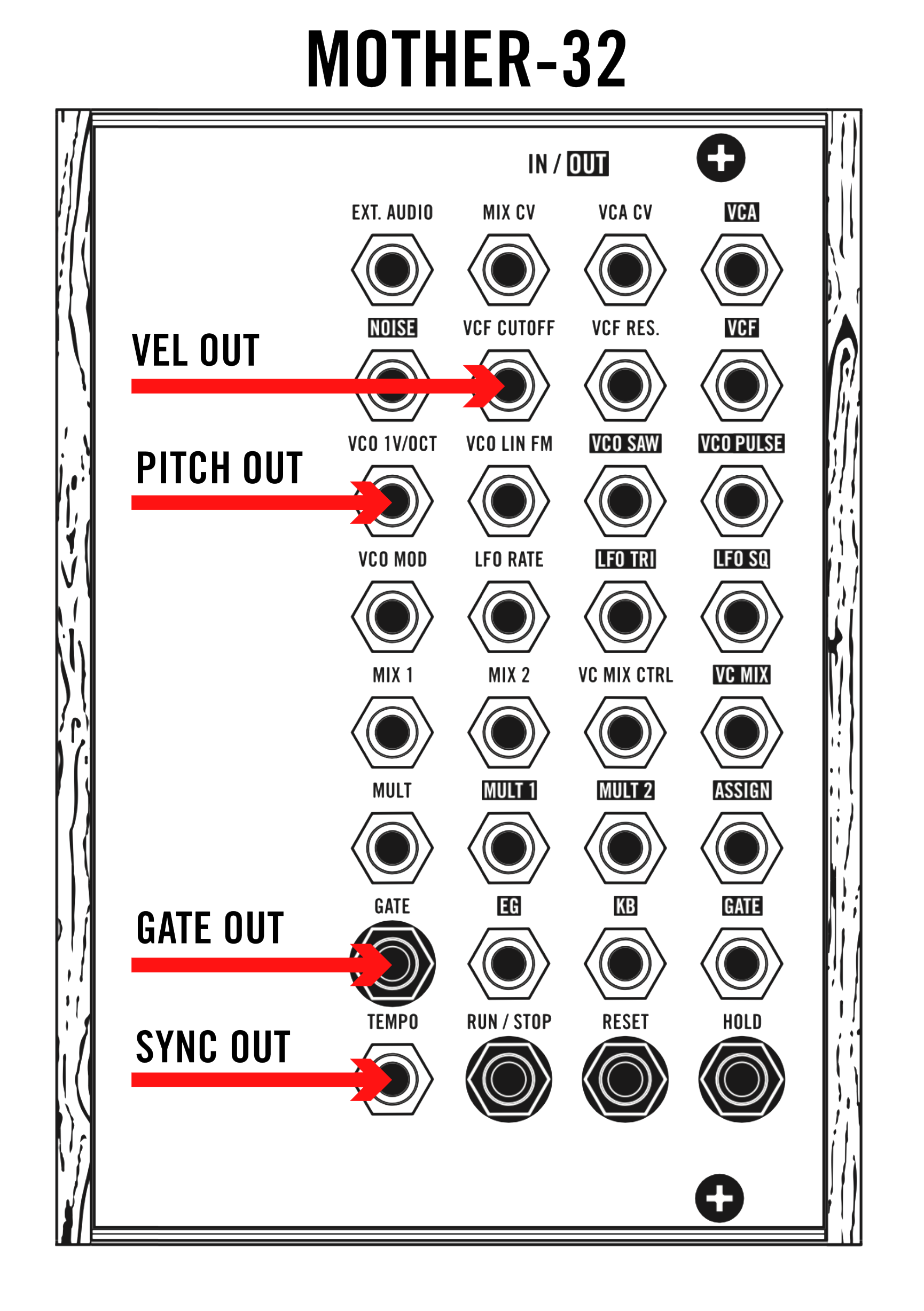
Using a MIDI keyboard to control a modular synthesizer is especially valuable when the system lacks an integrated keybed. Many modern MIDI controllers with CV functionality provide dedicated control‑voltage outputs that interface directly with analog modules. The three primary CV signals generated by these keyboards are gate, pitch, and velocity, each serving a distinct control function within the patch.
Gate
The gate signal functions as a note‑on/note‑off indicator. When a key is pressed, the keyboard outputs a high‑level voltage—commonly around +5 V—signaling that a note should begin. This output is typically patched to a module’s Gate or Trigger input, most often feeding the envelope generator that controls the VCA. The envelope responds to the incoming gate by shaping amplitude over time, enabling dynamic articulation.
Pitch
The pitch CV provides continuous voltage values corresponding to the notes played. This output is routed to the oscillator’s 1V/Oct input, the standard pitch‑tracking format for analog oscillators. As the voltage increases or decreases, the oscillator adjusts frequency accordingly, allowing the keyboard to play accurate melodies and harmonic structures.
Velocity
The velocity CV represents the force with which each key is struck. This voltage can be assigned to a variety of destinations—filter cutoff, VCA level, modulation depth, or any parameter with a CV input—to introduce expressive performance behavior. Modules may label these inputs as Velocity, Mod, or simply CV. Routing velocity enables nuanced, touch‑responsive sound shaping that mirrors the performer’s playing style.
Clocking Between Multiple Semi-Modular Synthesizers
Connecting semi‑modular synthesizers opens up a wide range of sound‑design possibilities and encourages experimentation with timing, modulation, and signal flow. One of the first steps in linking multiple hardware units is establishing a shared tempo reference, ensuring that all devices operate in sync and maintain stable gain staging.
Setting up the Master Clock
When working with several semi‑modular instruments, it’s essential to assign one device as the master clock. This unit provides the primary timing signal that all other devices follow. The synthesizer responsible for defining tempo or rhythmic structure should take on this role.
To configure the system, patch the clock output of the master device into the clock input of the other synthesizer(s). This distributes a consistent timing pulse across the setup, keeping sequencers, envelopes, and rhythm‑based functions aligned.
Clocking Example
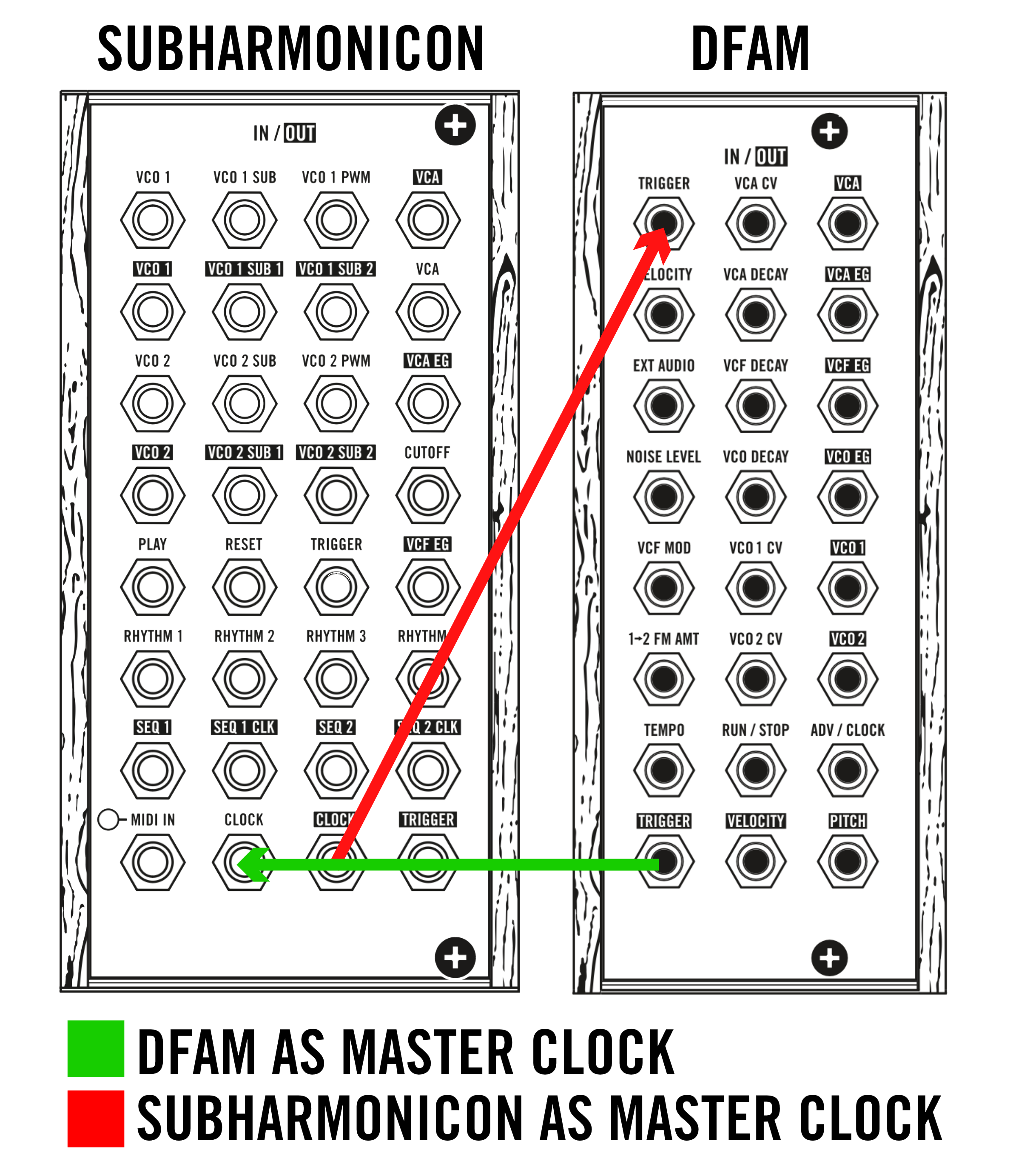
If the Subharmonicon is chosen as the master clock, connect its CLOCK OUTPUT to the TRIGGER INPUT of the DFAM. This forces the DFAM to follow the tempo generated by the Subharmonicon. For alternative rhythmic behaviours, you can also route TRIGGER, SEQ 1 CLK, or SEQ 2 CLK OUTPUTS from the Subharmonicon instead of the main clock output, each providing a slightly different sync response.
If you prefer the DFAM to act as the master clock, simply reverse the routing: patch the TRIGGER OUTPUT of the DFAM into the CLOCK INPUT of the Subharmonicon. This makes the DFAM the primary timing source, with the Subharmonicon following its pulse.
Bipolar & Unipolar Voltage
What is Unipolar Control Voltage?
Unipolar control voltages are signals that operate strictly within a 0 V to positive‑voltage range, most commonly 0–5 V or 0–10 V. Because they only move in a positive direction, unipolar CVs are well‑suited for parameters that do not require negative modulation. This makes them ideal for functions such as oscillator pitch, filter cutoff, and modulation depth, where negative values would have no meaningful or desirable effect. For example, when controlling oscillator frequency, a unipolar CV provides a stable, predictable pitch response without the need for negative voltage swings.
Applications of Unipolar CV
- Oscillator tuning — Used to set and track pitch across a defined tonal range.
- Filter control — Enables smooth cutoff sweeps without the risk of negative voltages producing unintended behavior.
- Envelope generation — Commonly used to shape amplitude or other time‑based parameters, ensuring consistent, positive‑only modulation.
What is Bipolar Control Voltage?
Bipolar control voltages span a negative‑to‑positive range, typically −5 V to +5 V. This bidirectional behavior allows for modulation that can push a parameter both above and below its neutral point. Bipolar CVs are essential for expressive, symmetrical modulation tasks such as pitch bending, LFO‑based modulation, and other effects that require movement in two directions.
Applications of Bipolar CV
- Pitch modulation — Enables upward and downward pitch shifts, creating vibrato, bends, and expressive phrasing.
- LFO control — Many LFOs output bipolar signals to modulate parameters like vibrato, tremolo, or panning, producing richer and more dynamic motion.
Attenuator & Attenuverter
An attenuator is a module that reduces the amplitude of an incoming signal—whether audio or control voltage—before it reaches its destination. It functions like a variable gain control, allowing you to scale a signal downward from its original level. This makes it especially useful when you need to moderate modulation depth or prevent a CV source from overpowering a parameter. For example, routing an LFO or envelope through an attenuator lets you fine‑tune how strongly it affects something like filter cutoff or oscillator pitch, enabling subtle, controlled modulation rather than dramatic shifts.
An attenuverter expands on this idea by offering both attenuation and polarity inversion. Instead of only reducing a signal’s level, it can also flip the signal around zero volts, turning positive voltages into negative ones and vice versa. This inversion capability opens up a wider range of modulation behaviors. When working with bipolar sources such as LFOs, an attenuverter allows you to reverse the direction of modulation. For instance, if an LFO is modulating a filter, inverting the signal changes the contour of the movement, producing alternate rhythmic or timbral effects that add complexity and variation to a patch.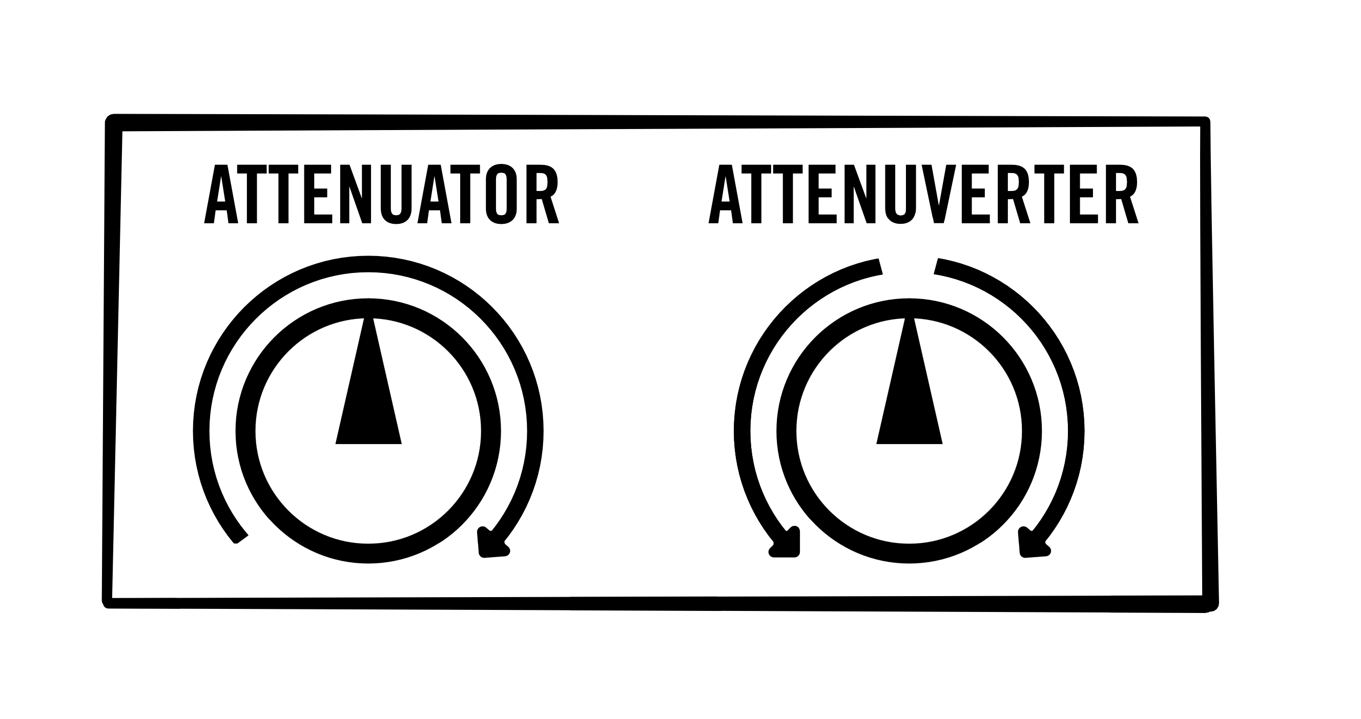
CV Offset
A CV offset is a fixed voltage added to an existing control‑voltage signal, shifting the entire signal upward or downward along the voltage axis. Instead of changing the shape of the CV, an offset changes its baseline, effectively redefining where the modulation begins.
When you apply a CV offset, you are altering the starting point of the signal. For example, if a modulation source produces a range of 0 V to 5 V, adding a +1 V offset shifts the entire range to 1 V to 6 V. The waveform itself remains identical in shape, but its minimum and maximum values move upward. This allows you to reposition the modulation so that it operates within a different functional range of the destination module.
CV offsets are especially valuable in patches where precise parameter placement is required. Instead of adjusting the entire modulation source or reconfiguring multiple modules, an offset lets you fine‑tune the operating point of a parameter with much greater accuracy. This is particularly helpful when working with modules that respond differently at various voltage thresholds or when combining multiple modulation sources that need to align correctly.
CV Guidelines (Voltage Height Standards)
When working with control voltages, it is essential to stay within the voltage specifications defined for each CV input on your instrument. These limits determine how accurately and safely a module can interpret incoming signals.
If a module receives a voltage lower than what it expects, its response will be incomplete or inconsistent. For example, if a VCA is designed to open fully at +10 V but your modulation source only provides +5 V, the VCA will never reach its maximum amplitude. The module will still function, but its behaviour will be restricted because the control signal cannot drive it through its full operational range.
Exceeding the recommended voltage range generally does not cause immediate damage, but repeatedly sending voltages higher than the specified limit can place unnecessary stress on internal components. Over time, this may reduce the long‑term reliability of the instrument. Using an attenuator or other voltage‑conditioning tool ensures that incoming CV remains within safe boundaries.
For detailed information on acceptable voltage levels for each patch point, consult your instrument’s manual. The manual provides the exact ranges required for safe operation and will help you apply control voltages effectively throughout your setup, ensuring stable performance and long‑term durability.
Was this article helpful?
That’s Great!
Thank you for your feedback
Sorry! We couldn't be helpful
Thank you for your feedback
Feedback sent
We appreciate your effort and will try to fix the article