
Matriarch’s filters operate in one of three selectable modes; SERIES, PARALLEL, or STEREO. Depending on the current setting of the FILTER MODE switch, VCF 1 has the ability to operate in either HIGH PASS or LOW PASS mode, while VCF 2 maintains its LOW PASS operation at all times. A stereo signal path is available from the filters onward.
Matriarch’s filters are based on the classic Moog 904A 24dB per octave voltage controlled low pass filter, which can be found on the Moog Model 10 Modular Synthesizer. Both VCA 1 & VCA 2 on the Matriarch operate at 24 dB per octave (4 pole), giving the synth a classic Moog filter slope.
TABLE OF CONTENTS
- Filter Mode
- HP/LP (Band Pass Filter) - Series
- LP/LP (True Stereo Signal Path) - Independent
- HP/LP (Notch Filter) - Parallel
Filter Mode
This three-position switch defines how VCF 1 and VCF 2 are configured, and how they will interact with each other.

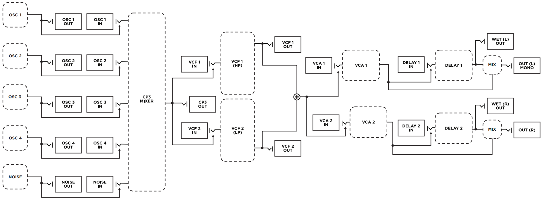
HP/LP (Band Pass Filter) - Series
In this mode, VCF 1 is configured as a HIGH PASS filter and VCF 2 is configured as LOW PASS filter. Signal passes from the Mixer module into VCF 1 (High Pass), and then is routed into VCF 2 (Low Pass). The MONO output signal from VCF 2 feeds both VCA 1 and VCA 2.
Band Pass Filter
High pass filters block out low frequencies, and low pass filters block out high frequencies. When the two filter types are combined in series with a shared cutoff frequency, they create a band pass filter.

Series Signal Path
Each stage processes the output of the previous one. Processing a HP into a LP in series is the foundation for creating a BAND PASS filter.
HP/LP Signal Flow

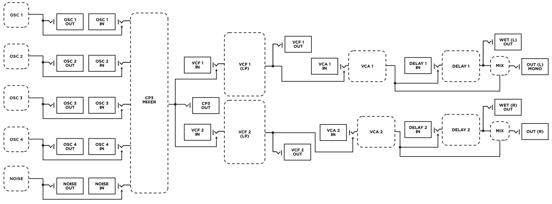
LP/LP (True Stereo Signal Path) - Independent
In this mode, VCF 1 and VCF 2 function independently as LOW PASS filters. Both receive the same signal from the Mixer module. VCF 1 is routed to VCA 1, and VCF 2 is routed to VCA 2.
This creates a TRUE-STEREO signal path to the outputs.
True Stereo Signal Path
A true stereo signal path means that the left and right audio channels are processed completely independently from start to finish, rather than being summed or partially combined at any stage.
LP/LP Signal Flow
HP/LP (Notch Filter) - Parallel
In this mode, VCF 1 is configured as a HIGH PASS filter and VCF 2 is configured as a LOW PASS filter. Both receive the same signal from the Mixer module, and their outputs are combined into a MONAURAL signal that feeds both VCA 1 and VCA 2.
Notch Filter

Parallel Signal Path
Signals are processed independently, then combined. Processing a HP into a LP in parallel is the foundation for creating a NOTCH filter.
HP/LP Signal Flow
Was this article helpful?
That’s Great!
Thank you for your feedback
Sorry! We couldn't be helpful
Thank you for your feedback
Feedback sent
We appreciate your effort and will try to fix the article